The notes on panoramic photographs in a recent number of the “B.J.” will no doubt have interested quite a fair proportion of readers; and in all probability many more will welcome some amplification of the subject. And as there appears to be very little literature on this fascinating phase of the photographer's art the following notes are penned with the hope they may at least help the novice, even if they fail in the more ambitions desire to stimulate the production of a scientific treatise on the principle invoked. The panoramic camera is a necessity: there can be no question of that, and although much good work can be done by joining up several ordinary photographs, there are cases where all the skill in the world will fall to make a presentable picture; and an example, of this failure occurs when we have a view including railway lines in the foreground. At each join the lines meet at an angle and as we are not accustomed to trams tracing pentagons and squares, we are offended by the view. In a panoramic picture of the same subject, the lines will appear as continuous curves; so we are not asked to imagine the impossible, and therefore the eye and sense are not offended. To the professional mind in doubt, the big group is the most important class of work to which this camera can be put and here it is clearly scores that no argument is needed. These groups of course, are arranged in an arc of a circle with the camera at the centre; and the general perspective of the recanting picture, may be likened to one taken with an ordinary camera and a very long focus lens whose axis is at right angles to the same group arranged in a straight line. Now whatever carping critics may say, the man at the end of a panoramic group will he far better pleased than if it had been a wide-angle group; for he is in the same perspective as the man in the middle and this will prove a blessing to the photographer who has to copy a single figure from a group for the purpose of enlargement, and alas! in very many cases, the only available source will be front one of those big military panoramic groups and whatever consolation father, mother or sister can get from the finished enlargement, it will be all the greater from the fact that their departed hero is delineated in tine which would not be the case in the figure were copies from near the end of a while-angle group.
The thing that is most objectionable about a panoramic view is when something that we know must necessarily be straight comes out in the photograph as a pronounced curve. There are two ways to avoid this: one is by the arrangement of the subject, as in the case of a group, or by the selection of the point of view. Now, in general a horizontal straight line, except when it radiates from the camera, appears in a panoramic photograph as a curve: and, conversely, there is a certain curve which, when in a horizontal piano with the camera at its origin, will always appear an a horizontal straight line; and if we know the nature of this curve, we shall be in a better position to order the arrangements for any particular photograph we wish to take.
Let us take a practical example:-Fig. 1 is a diagrammatic view of Ludendorff, on horseback, giving a farewell address to his troops; and perhaps adding a few words of advice and warning mi the disastrous consequences of a complication of Prussian microcephalism and Asiatic beriberi. In the ordinary panoramic parade photograph the men dwindle away towards each end of the picture, and form a strange curve that would remind a soldier more of some lamentable straggle with the theory of a trajectory than of invincible, Vandalia, martial glory and also it offends all our ideas of perspective. And besides, perhaps, Ludendorff would not like it; he might think yon were puking fan at him, and intended some sly allusion to "elastic fronts." The remedy is to get the valiant soldier to let you arrange the men; and to get this effect of straight lines vanishing to the horizon, as in Fig. 1. they will have to be arranged in the form shown in plan by
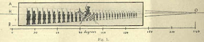

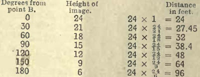
the heavy line in Fig. 2. If we are using a 12-in. lens; and decide to have the finished picture about 40 inches long, the group will have to be included in an angle of about 180 degrees; because12^=37¾ nearly, which will allow just a little margin each end. If we further decide that the nearest soldier shall be three inches high in the photograph, and the one at the remote end of the line one-quarter that being then, by the simplest arithmetic, the nearest man must be 24 feet from the camera, and the furthest one 86 feet; and, as the group is to include 180 degrees these two men and the camera will be all on the same straight line. This is shown t., scale in Fig. 2, where the position of the camera is given by o, and B and B’ are the places of the and men. The setting out of the rest of the curve is quite simple if we remember that the panoramic projection of the horizon is a straight line, and every length of a panoramic photograph represents an equal angle or number of degrees; that is to say, if three inches at the end of a Pangram represents 15 degrees, then also three inches from the middle will represent exactly the same angle, and if the line B O, joining the men's feet in Fig. 1, is to be straight, the vertical distance between it and H O must diminish by the same arithmetical amount for each equal length of the picture; and as the distances from the camera must be inversely as the height of the figures, we have the clue to every point of the curve. Now, let us calculate the distance of the curve from the origin o for every 30 degrees. As the total fall in height is to be 3-¾, and 30 is contained six times in 180, then

is the amount required; and in the table below the distances of the points are given in feet for every 30 degrees, while the heights of the image are given in eighths-of-an-inch, to avoid fractions and show better the regular decrease.
In regard to this table it may be observed that the product of the height and distance is a constant quantity. A group arranged in this way will, in the resulting Panorama, have the same general perspective as Fig. 1 though course each element of the picture will have the perspective peculiar to the lens with which it was taken.
Now if the lines AO and BO are continued they will meet outside the picture, at the vanishing point O n the horizon; and if we call the vertical distances between A and B h and the number of degree from H to O, which in this case will be 240 deg., then for every degree the height will decrease by; therefore at any angle ß. measuring from H. the bright of the figures will be: -

and the distance from the camera to the curve of this point will be: -

It will be been that is a constant quantity which we will call a; and a ß is a variable angle which we will call; then, substituting and patting r for the variable radius we have: -

,
and, clad in this classic garb, readers who have dwelt in the seventh heaven of mathematical bliss will recognize in old friend, the "reciprocal spiral." To show the nature of the complete curve it is continued in the diagram at each and by broken lines, and towards the origin it approximates more and more to a circle with every revolution it makes recording to the law –

where ra is the radius at the nth crossing of the initial line and by taking a and n of suitable dimensions we can get as near as we like to any tiled circle. By making is very small the whole curve approximates to the initial line; and if we take it small enough we have the special case of the radiating straight line. This from this spiral we can get in our photograph a right line at any degree, of obliquity and perhaps enough has been said to make clear the general law: -
The panoramic projection of a reciprocal spiral in a horizontal plane with the camera its origin is a straight line and only this carve or some special phase of it is so rendered.
But in all probability it would be as difficult to get a photographer to look at a formula of this kind as it would be get Ludendorff to let you arrange his men; so perhaps a better way would be to plot the curve to several valuations, then equal lengths; and this would give a rapid approximate way of finding what one wants.
Before leaving this subject there are several practical points consider. Where shall we put Ludendorff? In Fig. 1 it will be seen that the centre-line of the picture passes through the horse's head and therefore, he must be placed so that the mid-angular line in this case the 90 deg. line passes under the head of his charger. Another point to consider is what would happen if; instead of terminating the group at B and B we continued it along towards the originals far as the curve is

marked out in the diagram by the broken line, and also at the rather end along the straight for half a mile or so; and then starting the Circuit camera at the beginning of the group, let it run round for two and a half revolutions? Still keeping to the 12-in lens, we should want a 16-ft. film for the job; but to see the sort of thing we should get, draw a long rectangle in represent the picture (Fig. 40). The group will begin three tines over and end three times, and if we draw a straight line from the bottoms left-hand end of the rectangle to the horizon at the other end to show the line upon which the complete group is standing the diagram will be completed by a line of 240 deg. and one of 180 deg from the commencement of the picture and two lines of the same lengths at the end; and as these short

lines are necessarily repetitions of parts the long one, all live will consequently be parallel to each other.
The practical outcome of all this is what every user of a panoramic camera knows: avoid such a position that gives a straight line, which in perspective ought to be parallel with the ground line; if we can get to something like 45 deg. from this position the curvature will, as a rule, be quite
negligible; all radiating lines, and also parallels to these lines if a fair distance from the camera, will be straight in the resulting panorama because, like the circle, they are special phases of our spiral.
Knowledge of the rigid conditions for a straight line will do the operator no harm and even sometimes be helpful to the practical man.
When only a moderate angle is included in included in a panoramic view, it is not beyond realms of feasibility to bring the pictorial into ordinary perspective by spying: the only conditions necessary being to bend the negative into the same curve that it had during exposure; and then project the image by means of a lens at the centre of the curve on to a flat to a line passing through the centre of the curve and the middle of the negative. This is shown in Fit 3, where we may suppose the negative was taken with a lens at 12 inches focus, and is therefore bent into a circular arc of 12 inches radius, and is being copied with a lens of 6 inches focus, which will give us a copy corrected as regards perspective, and of the same size as if the negative had been taken in the ordinary way with a 12-in. wide angle lens. Of count, the corrected copy will be longer than the panoramic view. In regard to the optical system, it is not at all necessary to have an anastigmatic; some old-fashioned thing with a field as round as a football will do better; and perhaps a thin spectacle lens with a small stop right in contact with the glass best of all. Or, of course, the lens could be rotated during exposure; but then we should lose the advantage of roundness of field. Some years ago a lady took a picture of a castle in Scotland with an Al Vista camera, held so that the lens made a vertical sweep. The towers of the castle came out like barrels, but a correct bromide print was made in the way indicated above. A special optical system would have to be devised to cover anything more than a very moderate angle, and, in many cases, true perspective over a very wide angle would prove more objectionable than panoramic projection.
In the Cirkut camera we have great advantages: we can include any angle up to 360 degrees or more; we can focus; and we have usually three different foci to choose between; but, in the matter of range of time of exposure, it is the biggest sinner of all the panoramic cameras. The quickest exposure is literally too slow for a funeral, and the longest possible time you can give is too short for a dull subject on a dull day. In cameras of the Al Vista and Panorama class, we could tackle ordinary hand-camera subjects on a bright day; and for a still subject on a dull day we could fix the camera on a steady stand and increase the exposure to anything we liked by swinging the lens to and fro as many times as necessary. And on some patterns of the Al Vista a brake, in the form of an air vane, was fitted, which not only increased the exposure, but also amused the group while it was being photographed.
In the matter of fitting new lenses to panoramic cameras this, in general, is impractical, except in the case of the Cirkut camera, where a new lens will mean also a new set of pinions and the number of teeth to the pinions will be inversely as the foci of the lenses. There will be several points to attend to in making such a substitution, which are of more practical interest to the camera maker than the photographer.
In view of a recent patent for a camera in which the image is received on the inside of a cone, it may be as well to define panoramic projection as used in the above article as the projection by straight lines from points on the object through the centre of a vertical cylinder on to the cylindrical surface itself; the intersection of these lines with this surface forming the image, which is afterwards viewed when the cylindrical surface is spread out flat to form the panoramic picture.
C. J. STOKES.